| Driving A Liquid Crystal Shutter |
|
Many of our customers request samples of a simple liquid crystal display shutter that can pass or block light. Usually this light is in the visible spectrum, however occasionally we hear of applications where IR or UV wavelengths are involved. If your application is for a shutter that operates outside the visible spectrum, please let us know at the time you request your sample. This app note will give some general information on driving the LCD shutter, and is certainly not intended to show a circuit ready for a production environment. Once the basics are presented, the design can be readily adapted to your application. Feel free to change anything and everything, there are only a few basics to keep in mind:
The timing diagram above is shown for completeness, however it is not really necessary to understand it to make the shutter work. The diagrams clearly show the RMS sensitive nature of the device. If the square waves on the common and segment planes are in phase, the RMS voltage is 0 and the display turns off. If the two signals are out of phase, the RMS voltage is not zero and the display switches on (as long as the RMS voltage is greater than the threshold voltage of the fluid in the shutter that is.))
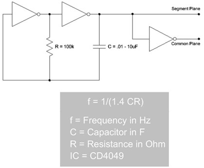
A sample drive circuit is shown above. It consists of a single CD4049 CMOS IC, and should only take a few minutes to construct. It consists of a simple free-running oscillator made from the two inverters on the left, and an additional inverter to provide the inverted backplane waveform. I'll leave it to you to calculate R and C to get the correct frequency. The Segment Plane and Common Plane outputs in the diagram go to the two contact ledges of the shutter, and for the purposes of this exercise are interchangeable, so don't worry which is which. If the sample shutter you received does not have wires connected to the contact ledges, a few alligator clips should do the job. Don't worry about scratching the Indium on the contact pads, it's pretty durable. Soldering wires to the contact ledges is a bit of a trick, as ITO solder and ultrasonic soldering pencils are necessary. Gluing the wires on is an option, but the adhesive you use should be conductive or it's liable to act as a pretty good insulator. I hope this helps with your design. If you have any further questions, please don't hesitate to call us at (440)232-8590 for further technical assistance. |