Pi Cell
(Optically Compensated Bend – OCB Cell)
The liquid crystal pi cell was first developed at Tektronix Corp. by Dr. Phil Bos in 1984. A pi cell LCD is generally used in applications where very fast switching cycle times are required. Pi cells also have an increased viewing angle, which is the result of the self-compensating nature of the cell structure. Pi cells have applications in 3D viewing, large screen TV’s and high speed optical shutters. The name comes from the fact that a pi cell has a 180 degree twist, instead of a 90 degree twist like a normal TN cell.
1) Response Time
The decrease in switching cycle time in the pi-cell lcd is accomplished by taking advantage of the fluid dynamics within the cell. A regular ECB cell has a uniform alignment of molecules with a pre-tilt angle in opposite directions on the front and rear substrates, also called anti-parallel alignment, as shown in figure 1a. (The molecules themselves are lying parallel to each other, but the glass substrates were rubbed in opposite directions, hence the name anti-parallel rub.)
When the electric field is switched off, the molecules in the mid-layers feel a torque, which causes a back-flow within the fluid layers as they try to return to their original state as shown in figure 2a. This back-flow tends to slow down the relaxation of the molecules and causes a bounce in the electro-optical response of the cell, thereby increasing the turn-off time.
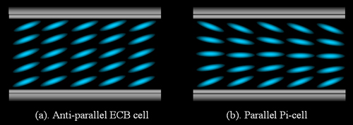
Figure 1. Comparison between conventional ECB cell and Pi-cell.
In the pi cell, the front and rear glass substrates are rubbed in the same direction, called parallel rub, as shown in figure 1b. (The molecules themselves are not lying parallel, but the glass substrates were rubbed in the same direction.) When the field is switched off, the molecules in the mid-layer do not feel a torque during relaxation as in the anti-parallel cell, as shown in figure 2b. There is therefore no bounce in the electro-optical response, resulting in a faster turn-off time.
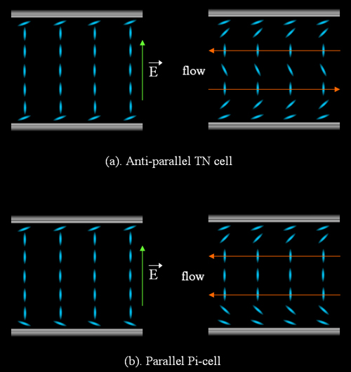
Figure 2. Flow direction comparison between conventional TN cell and Pi-cell.
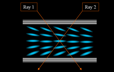
Figure 3. Wide viewing angle from the self-compensation nature of the pi cell.
2) Viewing Angle
The pi cell cell has a greater viewing angle because of the self-compensating structure of the cell itself, as shown in figure 3. In our figure, each of the incident light rays experiences a certain amount of retardation when going through the top half of the cell, and an equal but opposite amount of retardation when going through the bottom half of the cell. The equal but opposite retardations effectively offset each other, resulting in a wider than normal viewing angle.
3) Contrast Ratio
One of the potential disadvantages of the pi cell is that the on-axis contrast ratio is low because light going thru the cell exits eliptically polarized instead of linearly polarized as in a normal TN cell. The rear polarzer of the cell cannot perfectly block or pass the light, some of the light will always blead thru and reduce the contrast. This slightly eliptically polarized light cannot be corrected by changing the drive waveform or voltage, it is jut the nature of the cell.
It is therefore necessary to apply an optical compensation film to change the slightly eliptically polarized light back into linearly polarized light that will be blocked by the rear polarizer. This will restore both the high contrast ratio and viewing angle which the cell is capable of producting. This compensation film is a bit pricey, but the increase in contrast ratio it provides is significant.
4) Drive Waveform
To properly drive a pi cell it is first necessary to drive the cell from its “rest" state into the “pi" state. This voltage is usually very low, only a few volts. The frequency of the drive square wave is usually around 1 kHz or so. When in the "pi" state, the cells turn very transparent, and if fact that is how you tell when you have reached the pi state. By increasing the voltage further, the cell goes into saturation and turns opaque. We can offere some assistance when you are designing your drive circuit, please call one of our applications specialists for help.
I hope this app note helps you understand the pi cell a bit better. If you have any additional questions, please don’t hesitate to call us at (440) 232-8590 and talk to one of our applications specialists.