Liquid Crystal Display Materials
The materials used to make an LCD are highly specialized, and are manufactured by companies (mostly overseas) that specialize in the LCD industry. Once you understand the basic materials used, it will be much easier to understand the workings, and some of the problems, associated with the overall technology.
|
For now the the basic materials we will describe are: |
|
Compensation Films
Compensation films appear to be just another piece of polarizer that is placed over the top of the polarizer that is already on the display. The purpose and function however, are quit different. In order to understand comp films, it helps to understand the problem they are trying to solve. Once we understand the problem, we will talk about how the comp films solves it.
As light propagates through the liquid crystal cell, it is broken up into two modes which are generally elliptically polarized with the major axis of the polarization ellipse parallel to the nematic director (See Basics of LCD Operation). Only light that is linearly polarized propagates through the polarizers. With the addition of polarizers on each side a cell linearly polarized light will come out of it. To achieve this, the retardation of the cell (the birefringence times the distance through the cell, Dnd) must be much greater than the wavelength of the light divided by two. This condition is satisfied by the liquid crystal material used, which determines Dn, and by the thickness of the cell.
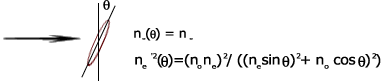
Once this condition is satisfied the bright state of the TN-cell in positive image mode has a very high luminance, but the dark state does not have a very low luminance. This is because the birefringence itself is dependent on the angle that the light propagates through the cell. Liquid crystals have two indices of refraction, an ordinary (no) and an extraordinary (ne’) and the birefringence is, Dn = ne’ - no. The ordinary index of refraction is the same for all angles of the incident wavefront. The extraordinary index of refraction directly depends on the angle between the incident wavefront and the director of the liquid crystal. The bright state is virtually unaffected by the viewing angle.
Angular Dependence of Dn.
The ideal TN-cell in positive image mode would have an activated state with a uniform director that is normal to the substrates. The birefringence for the director would be zero, both no and ne’ would have the value no at q = 0° . Within this cell, the polarization of the light would not change, and the crossed polarizers would extinguish the output. In a real world TN-cell in positive image mode, the cell has a director configuration that is uniform only through the center of the cell, see the image below. The liquid crystal molecules near the top and bottom glass are at some angle to the normal of the cell due to the anchoring energy. The activated director configuration is illustrated below.
How compensation Films Improve TN Display Viewing Angle
To compensate for the change in birefringence due to the director pattern close to the glass substrate, a film is created that mirrors the director pattern of the activated TN cell. This mirror image will change the birefringence in the opposite way the director does therefore the phase difference of the light coming out of the cell with the film will be the same as the phase difference of the light going into the cell and film combination.
In principle, the ideal compensation film would have the exact director configuration of the TN-cell in the activated state. This can be achieved by two types of compensation layers a passive (no voltage) liquid crystal cell with a director that mirrors the activated state of the TN-cell or a polymer sheet. One disadvantage to the LCD is the extra weight and thickness added. Such a passive LC would also be more difficult to manufacture than the polymer compensation film. The disadvantage to the polymer films is that it is difficult to manufacture one that closely mirrors the TN director.
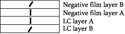
One film on the market that does come close to mirroring the TN director is the Fuji Wide View (WV) film. This film is made using a uniform splay of the director, which compensates for only part of the TN director. The molecules used to create the film are discotic in shape and have a negative birefringence. A compensation film is placed on each side of the TN-cell, therefore each film compensates for half the cell (refer to figure 3 below). A few drawbacks to the Fuji WV film are 1) The director pattern of the film does not have a twist to it like the director pattern of the TN and 2) The splay of the director pattern is over a smaller range of angles. The first can’t be changed while the range of angles can be adjusted.
In the figure below, notice that the net optical effect of the "A" layers is zero, and the Negative film layer "B" cancels the effect of the LC layer "B".
Negative Birefringence Films
Polarizers:
|
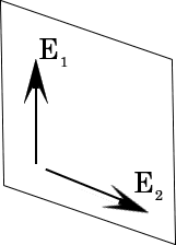
In the wave theory of light, optical radiation is regarded as an electromagnetic field that propagates in space. It is most conveniently represented by its electric field vector E(x,t) which is a function of both time and position. The electric field vector is perpendicular to the direction of wave propagation. The electric field vector is sometimes shown using its two orthogonal components, E1 and E2 in our diagram on the right Ordinary light from an incandescent bulb or from the sun is randomly polarized, that is, it includes waves that are oriented in all possible directions. This light is said to be unpolarized as the electric field vector is found in equal abundance in all possible directions. A polarizer is a material that is used to convert a randomly polarized ("un-polarized") beam of light into a polarized one, oriented in such a way that light with E2 along the x axis is absorbed, while the E1 along the y axis is transmitted. What emerges is that component of the original wave that had the y direction polarization, E1 in our diagram. In the example above, the polarizing direction is along the y axis. |
|
Positive image reflective liquid crystal displays have a polarizer applied to the front of the display and a reflector applied to the rear of the display. The liquid crystal molecules control the polarization state of beam of light polarized by the front polarizer. Controlling the orientation of the liquid crystal molecules will change the polarization of the beam. As the polarized light from the front polarizer passes through an un-energized display, it will be rotated 90 degrees by the liquid crystal and either absorbed or passed by the rear polarizer.
When the display segment is energized, the liquid crystal will follow the direction of the electric field and no longer rotate the polarized beam of light. Depending on the direction of the analyzer, the light will be either absorbed or passed. In the case of a positive image reflective display, this would produce a dark character on a light background. It is important to note that twisted nematic liquid crystal displays must have a polarizer applied to both the front and rear surfaces for them to function as useful devices.
Polarizers can be made of anisotropic media which transmit one component of the electric field vector and absorb the other component. This effect is known as dichroism. This effect can be a natural phenomenon, as in the mineral tourmaline, that exhibits a uniaxial birefringence, and has a dichroic ratio of about 10, that is it passes light about 10 times better in its preferred direction.
The first sheet polarizer for use with an LCD was developed by Erwin H. Land, and commercialized by Polaroid Corp. Today, sheet polarizers are usually made of PVA, or polyvinyl alcohol. The PVA sheet is stretched along an axis to align the needle-like molecules in its structure. The stretched films transmit one polarization component which is perpendicular to the direction of alignment, and absorb the other polarization component which is parallel to the direction of alignment.
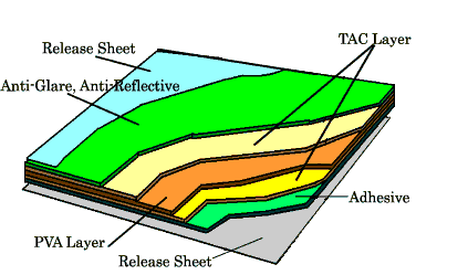 |
A cut-away view of a polarizer is shown on the left.
The critical polarizing layer, the PVA layer, is shown in orange. It is
surrounded on each side by a TAC layer. The TAC layer (Triacetyl Cellulose) acts
as a supporting layer, as it "captures" and helps stabilize the PVA.
On top of the front TAC layer, a layer of Anti-Glare or Anti-Reflective film can be applied to give the polarizer those properties in bright lighting conditions. On the bottom of the rear TAC layer is an adhesive to make the polarizer stick to the display. On the top and bottom of the polarizers are "release sheets" that protect the polarizer during manufacturing and handling. |
An ideal polarizer has a transmission of 100% of polarized light, i.e. a beam parallel to the transmission axis. The transmission would be 0% perpendicular to the transmission axis. So our theoretical perfect polarizer would transmit 50% of the light incident upon it. If two identical pieces of our theoretically perfect polarizers are put in series with one another, the intensity of the passed light would be somewhat reduced to a value of cos2 q, where q is the angle between the transmission axis of the two polarizers. So our pair of perfect polarizers will pass no light at all when placed at a 90o orientation to each other, and all of the light, 50% in this case, when placed 0o to each other.
In the real world the polarizers have transmission levels that are not perfect but are generally > 48%. They also do not polarize 100% of the light incident to the front surface, but have a polarizing efficiency of about 99% or greater. Thus our display segments will not be perfectly black when energized, but will have some bleed through.
Liquid Crystal Fluids
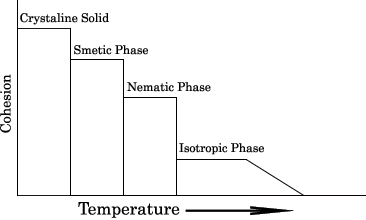
Liquid crystals are long chain organic molecules that sometime exhibit the properties of a liquid, yet have the long range ordering of a solid. The liquid crystalline state constitutes an intermediate phase (or mesophase) between solids and liquids. The fluids used for LCD's are called thermotropic liquid crystals as their properties change as the temperature goes up and down. If heat is added to the crystalline phase of the liquid crystal, it will transition into the smectic phase (melting point). As more heat is added, the liquid crystal will go through the nematic phase then finally into the isotropic phase. The transition temperature between the nematic and isotropic phase is called the clearing point of the fluid. See figure below. The clearing point of the fluid is a figure listed in the manufacturers data sheet, and is generally accepted as the upper end operating temperature of an LCD using that fluid.
Twisted nematic (TN), (STN) and active matrix displays operate in the nematic range. This phase is selected for its physical properties that give it the ability to "twist" light as it passes through the display. The fluids used by most manufacturers are actually mixtures of several different liquid crystals each chosen for its contribution to the desired properties. By mixing several liquid crystals together, a eutectic mixture will result, with the melting point depressed well below our desired operating temperature. A eutectic mixture is one that melts easily or at a lower temperature than any of its individual ingredients.
Liquid crystals are uniaxial. For example, if one
measures any one physical parameters of a water molecule, it can be shown that
the data for that parameter would be the same regardless of the direction along
which the measurements were taken. Liquid crystals differ in that the value of
most of its physical parameter are dependent on the direction along which they
are measured relative to the molecule itself. One can measure the index of
refraction of the molecule perpendicular to the long axis, and then make the
same measurement parallel to the long axis, and the two values would be
different. This is the index of refraction anisotropy, or
Dn of the liquid crystal, sometimes called the
birefringence. The figure at the top of the page in our discussion of
compensation films, demonstrates the concept of Dn.
This phenomenon also holds true for a number of other physical properties of the
fluid, most notably the elastic constants. Because liquid crystal molecules want
to align themselves parallel to one another, that is they have orientational
order, and they are uniaxial (anisotropic), we can make useful optical devices.
When you specify an LCD fluid for a given application, there are two critical
parameters that must be considered. Each fluid has many more characteristics,
but they can be ignored most of the time. Other critical parameters will usually
come out during the design process, and they can addressed at that time if
necessary. The two critical parameters are:
1) Working temperature range. - Most LCD fluids have a working temperature range of -40oC to +85oC in a direct drive mode. As +85oC is about +185oF, this temperature range covers the majority of both commercial and industrial applications. In applications where the display will be outdoor or in direct sunlight, a higher temperature range is recommended. Fluids that operated above +85oC used to be rather special, however by now they are readily available from almost all LCD manufacturers. By using some of the newer fluids that are designed for active matrix cells, a regular TN display can sometimes operate up to +125oC.
Working at the lower extremes of temperature is similar, but not quit as clear cut. LC fluids have a lower end operating temperature range that is determined by its viscosity. Like molasses, LC fluids get very thick and do not want to flow at low temperatures. Most fluids have a lower end operating temperature of about -40oC or higher. There are however, special formulations that can operate down to -55oC.
2) Voltage Threshold - The supply voltage of a drive circuit determines the amount of voltage available to the display. Most fluids will work fine in circuits that operate at +5 volts in a direct drive mode. The problem comes in when you do not have 5V available, or the circuit is multiplexed. For +3V applications there are special fluids that can be used. Make sure to tell us if you are working with a 3V battery so we can specify it in your design. Again, some of the newer fluids that are meant for TFT displays, with threshold voltages below +1V, can be used.
For highly multiplexed designs, the fluid selection becomes critical. In general the higher the multiplex rate, the higher the voltage requirements for a given fluid. When a display is multiplexed, the individual segments are time-division multiplexed, that is, you are only driving a segment to its "on" state for a portion of the total cycle. In a 3:1 mux, each pixel is only driven positive for one third of the time. The pixels are never really turned on all the way, and they never return to the full "off" condition. They exist in an intermediate state, not fully on or off, that results in greatly reduced contrast and viewing angle.
The voltage threshold is also very temperature dependent. The stated threshold in a catalog or data sheet is usually for room temperature operation, about 25oC. When a fluid gets near its lower end temperature range, the voltage threshold tends to creep up. Sometimes the creeping is very rapid, and there is almost a knee in the temperature response curve that is headed straight up. If you are concerned with the voltage threshold of your chosen fluid, the manufacturer can usually supply a response curve that shows how it shifts over the its temp range.
Conversely, at high temperatures, the voltage threshold goes down, so the drive voltage must be reduced or the display will "Ghost". There is a dv/dt spec that is usually available for a fluid that will give you an idea of how much you need to decrease the drive voltage at high temperatures.
If you have any questions concerning any of the technical issues discussed here, please don't hesitate to call or email us for assistance. Our expert engineering staff is available 9 to 5 EST.